Data Modelling and Entity Relationship Model
Data modeling is the process of creating a visual representation of an information system to communicate the relationships between different data elements. The Entity-Relationship (ER) model is the most widely used conceptual data modeling technique, providing a graphical representation that is easy to understand and communicate with stakeholders.
The Basics
A data model is a collection of concepts for describing data, relationships between data, and constraints on data.
Three Components of Data Models:
- Structure part: Rules that define how databases can be constructed (tables/records/objects)
- Manipulative part: Operations allowed on data (queries and updates)
- Integrity rules: Constraints that keep data accurate and consistent
Entity-Relationship (ER) Model:
The ER model is a conceptual data model that provides a graphical representation of database structure.
ER Building Blocks:
- Entity: Real-world object (Student, Course, Account)
- Attribute: Property of an entity (StudentID, Name, Age)
- Relationship: Association between entities (Student ENROLLS Course)
Entity Types:
- Strong Entity: Has its own key attribute
- Weak Entity: Depends on another entity for identification
Attribute Types:
- Simple vs Composite
- Single-valued vs Multi-valued
- Stored vs Derived
Relationship Types:
- One-to-One (1:1)
- One-to-Many (1:N)
- Many-to-Many (M:N)

Technical Details
DETAILED ER MODEL CONCEPTS:
1. Entities and Entity Sets:
An entity is a "thing" or "object" in the real world that is distinguishable from other objects.
- Example: A particular student, a specific course
An entity set is a collection of entities of the same type.
- Example: All students, all courses
Strong Entity:
- Has a primary key
- Can exist independently
- Represented by single rectangle
Weak Entity:
- Does not have a primary key
- Depends on another entity (owner/identifying entity)
- Represented by double rectangle
- Example: Order_Item depends on Order
2. Attributes:
Simple Attribute:
- Cannot be divided further
- Example: StudentID, Age
Composite Attribute:
- Can be divided into smaller parts
- Example: Name (FirstName, LastName), Address (Street, City, State, Zip)
Single-valued Attribute:
- Has one value for each entity
- Example: DateOfBirth
Multi-valued Attribute:
- Can have multiple values
- Represented by double oval
- Example: PhoneNumbers, Emails
Stored Attribute:
- Physically stored in database
- Example: DateOfBirth
Derived Attribute:
- Calculated from other attributes
- Represented by dashed oval
- Example: Age (derived from DateOfBirth)
3. Relationships:
A relationship is an association among entities.
Degree of Relationship:
- Unary (Recursive): One entity set (Employee manages Employee)
- Binary: Two entity sets (Student enrolls Course)
- Ternary: Three entity sets (Doctor treats Patient at Hospital)
Cardinality Ratios:
One-to-One (1:1):
- Each entity in A relates to at most one entity in B, and vice versa
- Example: Person has Passport
One-to-Many (1:N):
- Each entity in A can relate to many entities in B
- Each entity in B relates to at most one entity in A
- Example: Department has many Employees
Many-to-Many (M:N):
- Each entity in A can relate to many entities in B
- Each entity in B can relate to many entities in A
- Example: Student enrolls in many Courses, Course has many Students
Participation Constraints:
Total Participation (Mandatory):
- Every entity must participate in relationship
- Represented by double line
- Example: Every Employee must work in a Department
Partial Participation (Optional):
- Some entities may not participate
- Represented by single line
- Example: Not all Employees manage a Department
4. Keys in ER Model:
Super Key: Set of attributes that uniquely identifies an entity
Candidate Key: Minimal super key
Primary Key: Selected candidate key
Foreign Key: References primary key in another entity
5. Extended ER Features:
Generalization:
- Bottom-up process
- Combine similar entities into higher-level entity
- Example: Employee, Customer → Person
Specialization:
- Top-down process
- Divide entity into specialized sub-entities
- Example: Employee → Manager, Engineer, Clerk
Inheritance:
- Sub-entities inherit attributes from super-entity
Disjoint vs Overlapping:
- Disjoint: Entity belongs to at most one sub-entity
- Overlapping: Entity can belong to multiple sub-entities
Examples
EXAMPLE 1: UNIVERSITY ER DIAGRAM
Entities:
- STUDENT (StudentID, Name, Email, Major)
- COURSE (CourseID, CourseName, Credits)
- INSTRUCTOR (InstructorID, Name, Department)
- DEPARTMENT (DeptID, DeptName, Building)
Relationships:
- ENROLLS: Student M:N Course
Attributes: Semester, Grade - TEACHES: Instructor 1:N Course
- BELONGS_TO: Student N:1 Department
- WORKS_IN: Instructor N:1 Department

EXAMPLE 2: WEAK ENTITY
Strong Entity: ORDER (OrderID, OrderDate, CustomerID)
Weak Entity: ORDER_ITEM (ItemNumber, Quantity, Price)
- ORDER_ITEM depends on ORDER
- Partial key: ItemNumber
- Full key: OrderID + ItemNumber

EXAMPLE 3: COMPOSITE AND MULTI-VALUED ATTRIBUTES
EMPLOYEE Entity:
- EmployeeID (simple, key)
- Name (composite: FirstName, MiddleName, LastName)
- DateOfBirth (simple, stored)
- Age (simple, derived from DateOfBirth)
- Address (composite: Street, City, State, Zip)
- PhoneNumbers (multi-valued)
- Email (simple)
EXAMPLE 4: CARDINALITY EXAMPLES
1:1 Relationship:
PERSON ──1:1─── PASSPORT
Each person has one passport, each passport belongs to one person
1:N Relationship:
DEPARTMENT ──1:N─── EMPLOYEE
One department has many employees, each employee works in one department
M:N Relationship:
STUDENT ──M:N─── COURSE
One student enrolls in many courses, one course has many students
EXAMPLE 5: COMPLETE ER TO RELATIONAL MAPPING
ER Model:
STUDENT (StudentID, Name, {PhoneNumbers})
COURSE (CourseID, CourseName)
ENROLLS (Student M:N Course, Grade)
Relational Schema:
STUDENT(StudentID PK, Name)
STUDENT_PHONE(StudentID FK, PhoneNumber)
COURSE(CourseID PK, CourseName)
ENROLLMENT(StudentID FK, CourseID FK, Grade)
PRIMARY KEY (StudentID, CourseID)
Real-World Use
PRACTICAL ER MODELING STEPS:
-
Requirements Analysis:
- Interview stakeholders
- Identify entities (nouns)
- Identify relationships (verbs)
- Identify attributes
- Identify constraints
-
Drawing ER Diagram:
Tools:
- Draw.io (free, web-based)
- Lucidchart (cloud-based)
- MySQL Workbench (database-specific)
- ERDPlus (educational)
- Microsoft Visio (commercial)
- ER Modeling Example - Library System:
Requirements:
- Library has books
- Members borrow books
- Books have authors
- Members have multiple phone numbers
- Track borrow date and return date

Entities:
BOOK (ISBN, Title, Publisher, Year)
MEMBER (MemberID, Name, Address, JoinDate)
AUTHOR (AuthorID, Name, Country)

Relationships:
WRITTEN_BY: BOOK M:N AUTHOR
BORROWS: MEMBER M:N BOOK (BorrowDate, ReturnDate, Status)

Multi-valued:
MEMBER has PhoneNumbers
- ER to SQL Implementation:
-- Strong entities
CREATE TABLE Book (
    ISBN VARCHAR(13) PRIMARY KEY,
    Title VARCHAR(200) NOT NULL,
    Publisher VARCHAR(100),
    Year INT
);

CREATE TABLE Author (
    AuthorID INT PRIMARY KEY AUTO_INCREMENT,
    Name VARCHAR(100) NOT NULL,
    Country VARCHAR(50)
);

CREATE TABLE Member (
    MemberID INT PRIMARY KEY AUTO_INCREMENT,
    Name VARCHAR(100) NOT NULL,
    Address VARCHAR(200),
    JoinDate DATE DEFAULT CURRENT_DATE
);

-- M:N relationships become junction tables
CREATE TABLE Book_Author (
    ISBN VARCHAR(13),
    AuthorID INT,
    PRIMARY KEY (ISBN, AuthorID),
    FOREIGN KEY (ISBN) REFERENCES Book(ISBN),
    FOREIGN KEY (AuthorID) REFERENCES Author(AuthorID)
);

CREATE TABLE Borrowing (
    MemberID INT,
    ISBN VARCHAR(13),
    BorrowDate DATE,
    ReturnDate DATE,
    Status VARCHAR(20),
    PRIMARY KEY (MemberID, ISBN, BorrowDate),
    FOREIGN KEY (MemberID) REFERENCES Member(MemberID),
    FOREIGN KEY (ISBN) REFERENCES Book(ISBN)
);

-- Multi-valued attribute becomes separate table
CREATE TABLE Member_Phone (
    MemberID INT,
    PhoneNumber VARCHAR(15),
    PRIMARY KEY (MemberID, PhoneNumber),
    FOREIGN KEY (MemberID) REFERENCES Member(MemberID)
);
- Best Practices:
- Start simple, add complexity gradually
- Validate with stakeholders at each step
- Use meaningful entity and attribute names
- Document business rules and constraints
- Avoid redundancy in the ER model
- Consider future extensions
- Use standard notation consistently
For exams
IMPORTANT EXAM QUESTIONS:
-
What is data modeling? Explain the three components of a data model.
Structure, Manipulative, Integrity rules -
Explain the Entity-Relationship (ER) model with its basic components.
Entities, Attributes, Relationships -
Distinguish between strong and weak entities with examples.
Strong: Independent, has primary key
Weak: Dependent, no primary key -
Explain different types of attributes with examples.
Simple, Composite, Single-valued, Multi-valued, Stored, Derived -
What are the different cardinality ratios in relationships? Explain with examples.
1:1, 1:N, M:N with real-world examples -
Explain participation constraints (total and partial) with examples.
Total (double line), Partial (single line) -
Draw an ER diagram for a [given scenario, e.g., Hospital Management System].
Identify entities, attributes, relationships, cardinalities -
What are the rules for converting ER diagrams to relational tables?
- Entity → Table
- 1:1, 1:N → Foreign key in appropriate table
- M:N → Junction table
- Multi-valued attribute → Separate table
- Weak entity → Include owner's key
-
Convert the following ER diagram to relational schema: [diagram provided]
-
Explain specialization and generalization in ER model.
Top-down vs Bottom-up, IS-A relationships
QUICK REVISION:
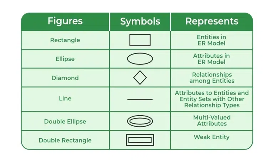
• Entity = Real-world object (Rectangle)
• Attribute = Property (Oval)
• Relationship = Association (Diamond)
• 1:1 = One to One
• 1:N = One to Many
• M:N = Many to Many (needs junction table)
• Strong Entity = Single rectangle
• Weak Entity = Double rectangle
• Multi-valued = Double oval
• Derived = Dashed oval
Key points
KEY TAKEAWAYS:
✓ Data modeling creates visual representations of information systems
✓ ER model uses entities, attributes, and relationships to represent data structure
✓ Strong entities have their own key; weak entities depend on owner entities
✓ Attributes can be: simple/composite, single-valued/multi-valued, stored/derived
✓ Cardinality ratios: 1:1, 1:N, M:N determine relationship multiplicities
✓ Total participation (mandatory): double line; Partial participation (optional): single line
✓ ER diagram symbols: Rectangle (entity), Oval (attribute), Diamond (relationship)
✓ ER to Relational mapping rules:
- Entity → Table
- 1:N → Foreign key in "many" side
- M:N → Junction table
- Multi-valued → Separate table
- Weak entity → Include owner's key
✓ Extended ER features: Generalization, Specialization, Inheritance
✓ Tools: Draw.io, Lucidchart, MySQL Workbench for ER modeling
✓ Best practices: Validate with stakeholders, use standard notation, document constraints
REMEMBER: ER modeling is the bridge between requirements and implementation. A good ER diagram simplifies database design and ensures all stakeholders understand the data structure!