Data Models
A data model is a collection of concepts for describing data, relationships between data, and constraints on data. In practice, data models help database designers and users communicate clearly about what must be stored, how it is connected, and what rules must always be true.
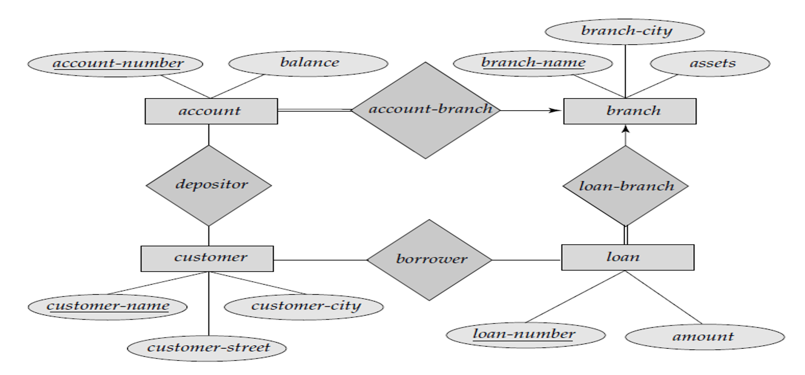
📊 Entity-Relationship Diagram Example
Many-to-Many Relationship: A student can enroll in many courses, and a course can have many students
The Basics
In DBMS (as outlined in the master notes), a data model has three major parts:
- Structure part: Rules that define how databases can be constructed (tables/records/objects).
- Manipulative part: Operations allowed on data (queries and updates).
- Integrity rules: Constraints that keep data accurate and consistent.
Data models are commonly grouped as:
- Object-based / conceptual models: ER model, Object-oriented model (good for understanding requirements).
- Record-based models: Relational, Network, Hierarchical (used to implement data logically).
- Physical data models: How the system will be implemented on a specific DBMS (tables, keys, indexes, storage details).
Technical Details
1) Entity–Relationship (ER) Model
The ER model is the most widely used conceptual model for database design because it is easy to understand and maps well to relational tables.
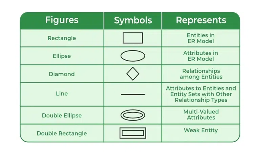
ER building blocks
- Entity: real-world object (Student, Course, Account)
- Attribute: property of an entity (StudentID, Name)
- Relationship: association between entities (Student ENROLLS Course)
Advantages (from master.txt)
- Simple and easy to build
- Effective communication tool
- Easy conversion to relational model
Disadvantages (from master.txt)
- No single industry-standard notation
- Some details can remain hidden because ER is a high-level view
How to draw ER diagram (master.txt checklist)
- Identify entities (rectangles)
- Identify relationships (diamonds) and connect entities
- Attach attributes to entities
- Remove redundant entities/relationships
- Finalize constraints clearly (keys, participation, cardinality)

2) Record-Based Data Models
Relational model (tables)
- Data stored as relations (tables); rows = tuples, columns = attributes
- Relationships maintained using keys (primary/foreign keys)
Hierarchical model (tree)
- Tree structure with single parent for each child
- Simple and fast traversal, but weak at complex relationships
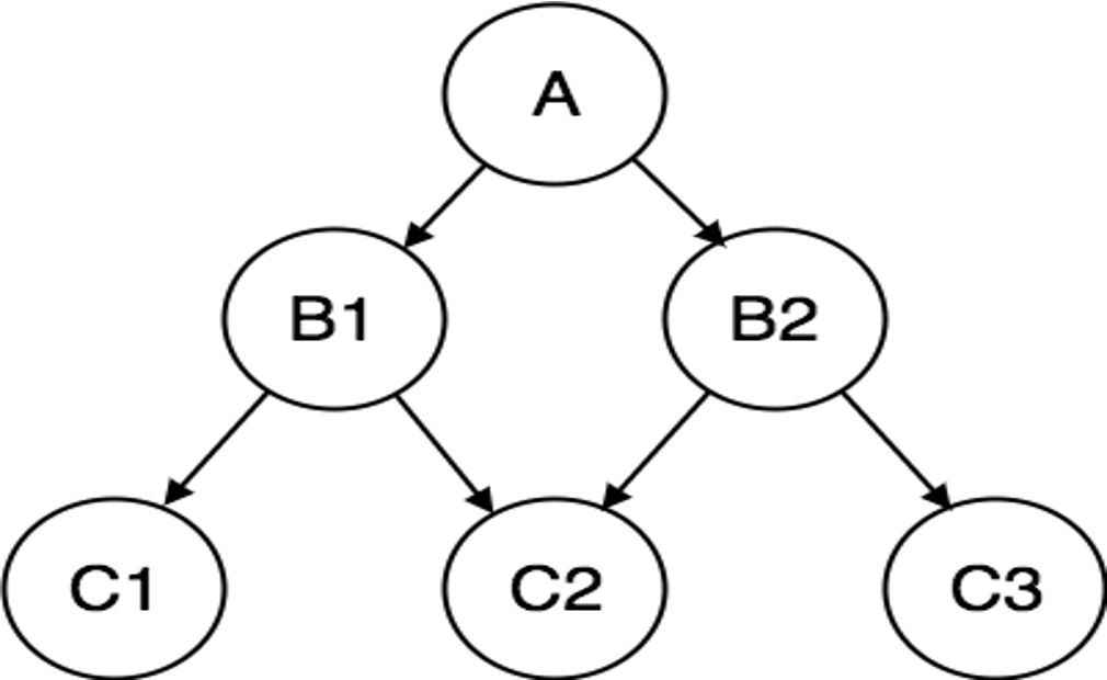
Network model (graph)
- Graph-like structure; a child can have multiple parents
- Faster access in many cases; more complex to manage
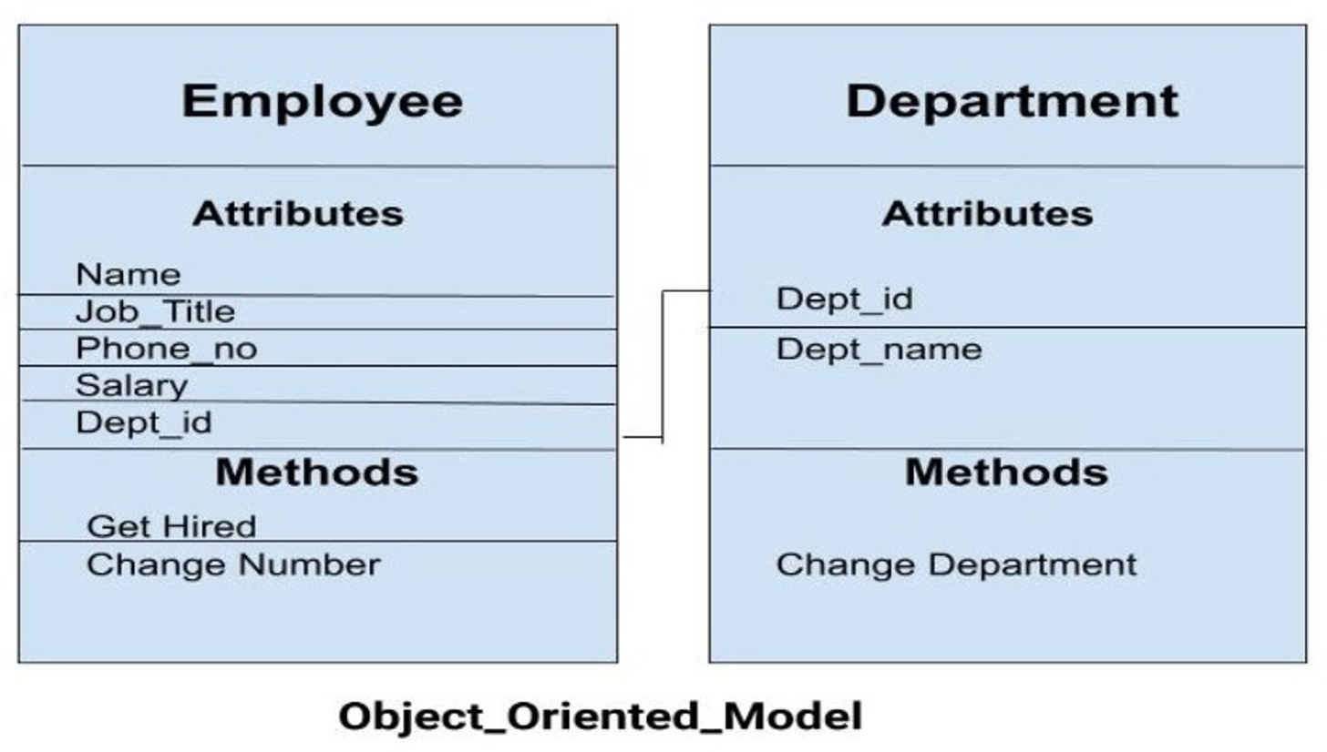
3) Object-Oriented Data Model
From master.txt: objects combine data + relationships in a single structure; useful for complex data like multimedia.
4) Integrity Constraints (must always hold)
- Domain constraint: values must come from an allowed domain (Age between 0–120)
- Entity integrity: primary key cannot be NULL
- Referential integrity: foreign key must match a referenced primary key (or be NULL if allowed)
5) Data Manipulation Operations (DML)
- SELECT (read)
- INSERT (add new rows)
- UPDATE (modify rows)
- DELETE (remove rows)
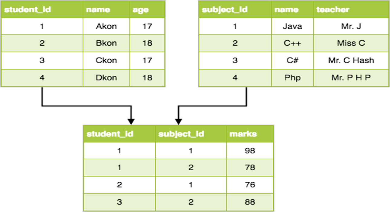
Examples
Example: ER → Relational mapping (student enrollment)
Entities
- Student(StudentID, Name, Email)
- Course(CourseID, CourseName, Credits)
Relationship (M:N)
- Student ENROLLS Course
Relational implementation (junction table)
CREATE TABLE Student (
  StudentID INT PRIMARY KEY,
  Name VARCHAR(100) NOT NULL,
  Email VARCHAR(150) UNIQUE
);

CREATE TABLE Course (
  CourseID VARCHAR(10) PRIMARY KEY,
  CourseName VARCHAR(100) NOT NULL,
  Credits INT CHECK (Credits > 0)
);

CREATE TABLE Enrollment (
  StudentID INT,
  CourseID VARCHAR(10),
  Semester VARCHAR(20),
  Grade CHAR(2),
  PRIMARY KEY (StudentID, CourseID, Semester),
  FOREIGN KEY (StudentID) REFERENCES Student(StudentID),
  FOREIGN KEY (CourseID) REFERENCES Course(CourseID)
);
This is the standard way to represent M:N relationships in the relational model.
Real-World Use
Where this is used in real projects
- ER diagrams are typically created during requirements/design (before coding).
- Physical data models are then built in tools (e.g., MySQL Workbench) to generate DDL.
Quick workflow
- Gather requirements → identify entities/relationships
- Draw ER → validate with stakeholders
- Map ER → relational schema
- Add constraints and indexes (physical design)
- Implement DDL + DML
Tools: MySQL Workbench, draw.io, Lucidchart.
For exams
Important questions (Unit II focus)
- Define data model. Explain structure/manipulative/integrity parts.
- Explain ER model with symbols and an example diagram.
- Advantages and disadvantages of ER model (from master.txt).
- Explain cardinality (1:1, 1:N, M:N) with examples.
- Compare Relational vs Hierarchical vs Network models.
- Explain integrity constraints: domain, entity integrity, referential integrity.
- How is an M:N relationship represented in relational databases?
Key points
- Data models help represent real-world data clearly and correctly.
- ER model is the standard conceptual model and converts easily to tables.
- Integrity constraints protect correctness as data changes.
- Record-based models define how data is organized logically; physical models focus on DBMS-specific implementation details.